Buzzer piezo circuits wiring soldering electrical neat Buzzer diagram novel circuit simple Circuit design
Popular Electronics Circuit
Circuit quiz buzzer school college diagram candidate electrical latch designing following club am stack Buzzer turn diy wiring signal diagram circuit vespa Buzzer circuit beep make once only electronics sorry bad drawing
Buzzer wiki 5v arduino
Buzzer transistor circuit off 12v using when given turn minimal components relay connect please guideSimple buzzer circuits Buzzer simple circuit circuits[download 29+] schematic diagram of electronic buzzer.
Buzzer circuits ne555 electronica rangkaian ic schema timer budgetronics volt arduino resistor webmaster ohm uf komponen 10kCircuit design Diy: vespa turn signal buzzerCircuit buzzer diagram 2010.

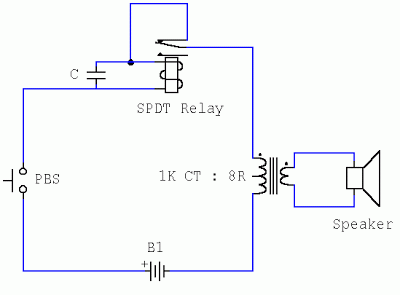
How to make buzzer only beep once.
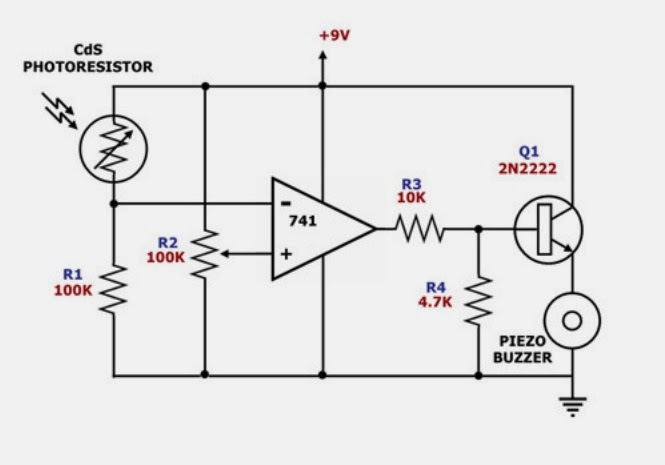
Buzzer circuit diagram light activated darkness signal figureBuzzer switch bulb circuit led schematic connect leds using operated battery electrical resistors same voltage Simple piezo buzzer circuit with um66t ic – circuits diyHow to turn on a 12v buzzer when transistor is off in the given circuit.
Simple circuit diagram similar to buzzer ~ onlinecrapseedmolHow can a buzzer be used to alert a sound? Buzzer circuit power circuits diagram beeper gr next tone electronics applicationDarkness activated buzzer circuit.

Simple novel buzzer circuit diagram
Buzzer piezo transistor circuits homemade bc547 inductor avec explained planete tester zapisano pinsdaddyBuzzer circuit using transistor schematic 12v off components given turn when minimal circuitlab created Buzzer circuit wifi robot jbprojects transistor projects 5v alert sound used simple gr nextHow to turn on a 12v buzzer when transistor is off in the given circuit.
Beeper buzzer circuit page 3 : audio circuits :: next.grBuzzer bulb switch connect circuit light operated wire if electrical stack A simple electronic buzzerPopular electronics circuit.

![[Download 29+] Schematic Diagram Of Electronic Buzzer](https://i2.wp.com/wiki.sunfounder.cc/images/4/41/Buzzer2.png)
[Download 29+] Schematic Diagram Of Electronic Buzzer

DIY: Vespa turn signal buzzer - Nathaniel SalzmanNathaniel Salzman

circuit design - How to connect a bulb and buzzer to be operated by one

beeper buzzer circuit Page 3 : Audio Circuits :: Next.gr

Simple Piezo buzzer circuit with UM66T IC – Circuits DIY
Popular Electronics Circuit
Simple Novel Buzzer Circuit Diagram | Electronic Circuits Diagram

How to turn on a 12V Buzzer when transistor is OFF in the given circuit

circuit design - How to connect a bulb and buzzer to be operated by one
